RED-CROWED CRANE RIG
- mc217227
- Mar 15, 2021
- 7 min read
Updated: Apr 30, 2021
To begin this project, purchase and download this model from CG Trader:
Stripping the file contents back to the mesh is where I shall begin.

LEG JOINT PLACEMENT


ORIENTING LEG AND FOOT JOINTS


Re-working the crane foot
After setting up an FK IK system for the right leg, it became apparent that there was little control over the toes and foot. It is time to try a new way of setting up a bird foot using additional joints and the use of custom attributes and set driven keys.
Setting up initial joints and their IK's
Run a rotate-plane solver IK from the thigh joint to the ankle joint. Place a single-chain solver from the ankle to the ball of the foot and another single-chain solver from the ball to the toe end joint. From adding these three IK's there will be three locators created; select these locators and shift select them then shift select the foot control to parent. (shift -> 'P')
l_ankle_ik
l_foot_ik
l_toe_ik
group these three IK's to the foot_ctrl
create custom attributes on the foot_ctrl
Heel
Toe tap
Ankle
Swivel
Select all IK handles and group them. They should look like this in the outliner,
Swivel pivot controlling IK rotation in Y axis
Foot hierarchy in outliner once all pivot groups have been connected to custom attributes

Connection Editor for Foot
Swivel attribute is the only attribute that requires the Rotate Y to be used for the foot setup.
Adding custom attributes allows animations to quickly select desired joints and appendages to move.

Adding Knee Control
Snap the pivot to the knee joint by holding down 'v' and Delete By Type History and Freeze Transformations. Shift select the 'ankle IK' and the new knee control and click -> constrain -> pole vector.
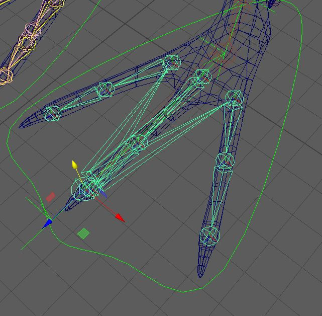
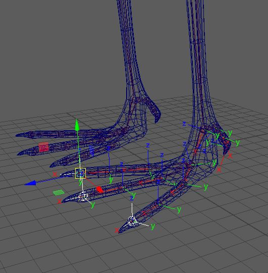
Parent toe joints (digits) to main toe joint. This enables all from digit joints to move in unison along the translate and rotate axis.
The locator is at the main toe joint which drives the rotation for the entire foot.
Demonstrating the parented toe joints using the custom attributes. (Below)

WING JOINT PLACEMENT
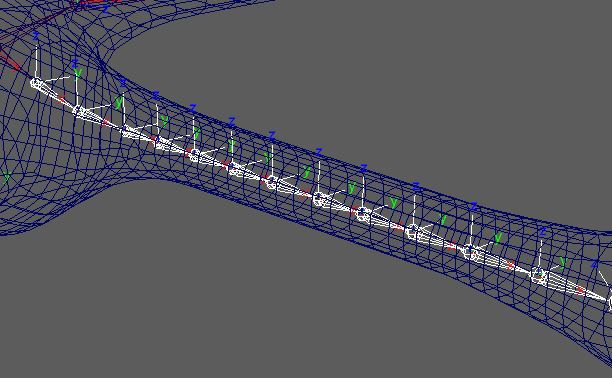
Placing down individual wing joints from an orthographic top view give the accuracy needed to ensure each joint sits nicely within its feather mesh. Changing views to Orthographic front, drag the mouse over the newly placed joints and selecting 'W' to move all of the joints along the y axis allows for correct placement.
WING VARIATION #2- CONTROLLERS AND CONNECTION EDITOR
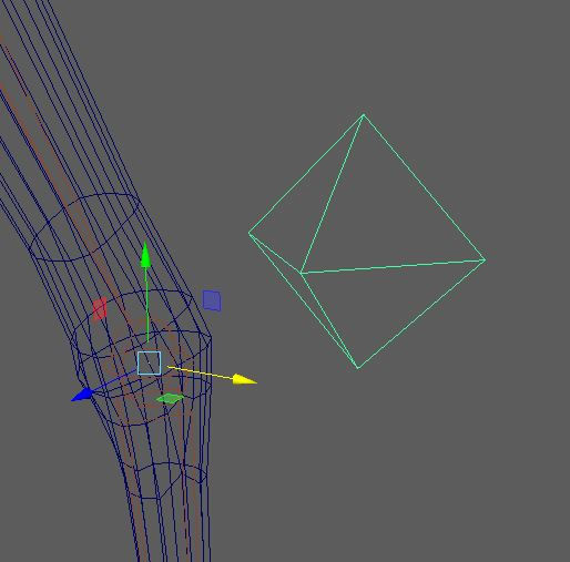
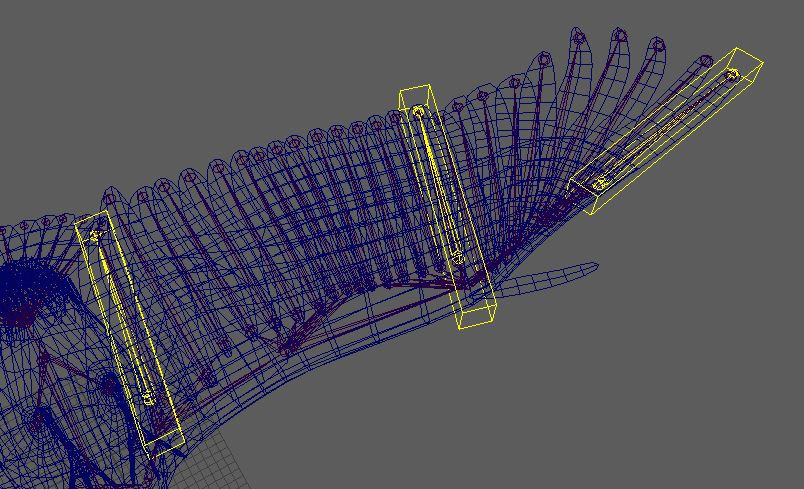
Referring to diagrams featured on the research page for this Crane rig, it is important to establish three major 'controller' wing joints. These three joints shall use MEL script to instruct the feather joints in-between how far to splay out once the controller joints are rotated. The three joints must be located around wing joints that naturally fold. Notice the middle joint (highlighted white) is placed by the metacarpal joint, this will give the most influence on the intermediate feather joints when rotated.


ORIENT WING JOINTS

Feather splaying: ISSUE, Blend Colour Utility Nodes (Wing Variation #2)
A blend colour Utility Node allows you to use 3 number inputs together to create one output, it using can use numeric x,y,z values which makes it ideal to implement into this new variation.

Ensuring that all feather joints have 0 rotation values, open up the Hypershade window. Click Tab and type into the seachbar 'BlendColor' and click into the Hyperhade UI, the node should be loaded.
Connection Editor
Open windows -> General Editors ->Connection Editor.
Load the blend colour node on the right of the connection editor and load the yellow control feather on the Left.
Plug the control feather's rotation values into the 'Color1' Blendcolor RGB values. The screengrab below shows the feathers being connected.


Select the second control feather joint and load this on the left of the Connection Editor. Plug this feathers rotation values into 'Color2' input. For the third numerical input, select the intermediate feather and load it onto the right of the connection editor. Turn on the left non-keyable attributes for the BlendColor and select 'output'. Connect the Output RGB values the the x,y,z feather values.
Selecting a wing control, go into the channel box editor and 'add attribute', name this attribute 'Wing_fold' and set and min and max float value of your choosing, -5 and 5 should be suitable.
Using Set Driven Keys, make the wing control the 'Driver' and the wing controls translate and scale attributes the 'Driven'. This will enable you to fold and extend the wing outwards once you toggle your Wing_fold attribute and click Key.


Evaluation of wing variation #2
After setting up the wing control with an IK, I was able to see how well the Blend Color Utility Node integrates into the wing motion. When extending the feathers they appear well spaced yet pulling the wing control inwards, the feather groups remain to bunch together unless manually grabbing one of the yellow feather controls and rotating it to see the Utility Node function. This variation gave me the opportunity to splay some feathers as groups but did not allows for the entire wing the have even feather movement. I shall be using the Blend colour Utility Node for other rigging exercises, unfortunately this variation shall not be used for my final rig due to the lack of unified movement it gives when manipulating the wig control.
WING VARIATION #3- Using IK Spline and Clusters
After evaluating wing variation 2, there is still room for opportunity to make the feathers splay outwards and have 'lift' and 'drag' by using custom controls. By drawing an EP Curve along the edge of the left wing, freezing transforms and deleting by type history, you can use this as a custom control to drive feather 'lift' and 'drag'.
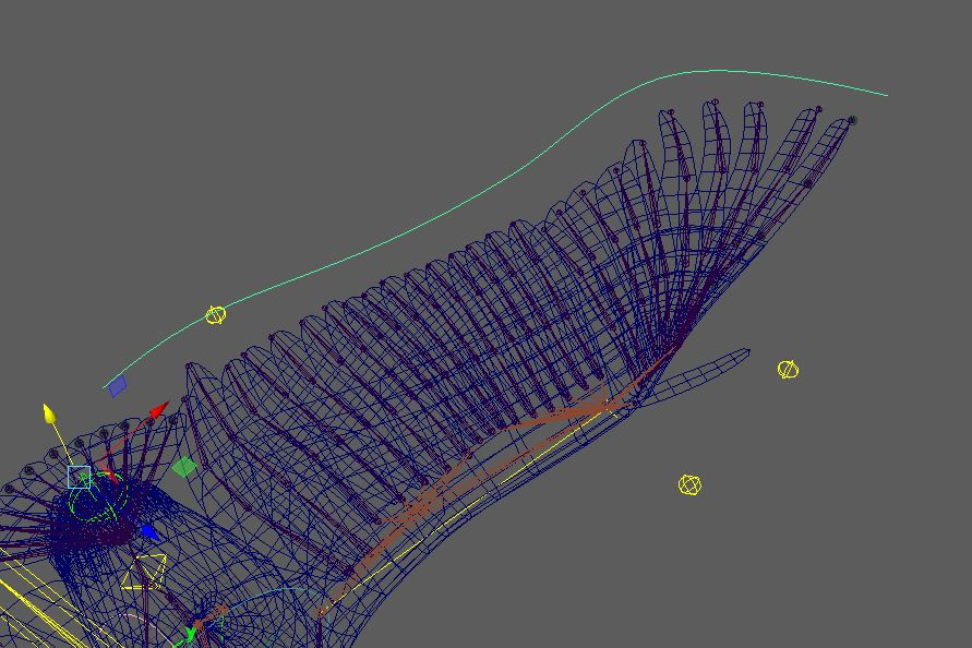

Using NURBS Curves with clusters parented within their hierarchy, there is reasonable feather manipulation.
Each feather joint has its own IK Spline chain and two clusters parented to the latter two joints. The clusters in the centre are parented to a custom EP curve control which create lift and weight once moved along the Y axis.
Feathers have centred pivots and are oriented at an angle so that once the wing is folded there is minimal overlap and gives a natural look to feather placement.

Neck
Neck joints are oriented on the x,y,x axis in the orientation settings. For the neck use an IK Spline handle to control the neck joints' controls. Create a bunch of NURBS curves and parent them to the neck joints of the rig. These curves once rotated shall be under the influence of the Spline Handle and give you the ability to move the neck around evenly without hard rotation angles. Weight painting the neck joint closest to the head control may be necessary as there could be undesirable creasing. After touching up weight pints, the neck should rotate smoothly.


TAIL
When orienting the joints, ensure that the base has world orient settings so the rest of the joints can rotate along the x,y,z axis cleanly. With the tail control, v snap the control to the tail base joint and constrain parent it.
Using NURBS curves, create a custom attribute (just like the wing control) , open set driven keys and open up the connection editor. Altering the y and x rotation values will allow you to splay the tail feathers in and out as you toggle the min and max values in the attribute editor.

The min max values set for the tail attribute are 0 to 5.
Grouping clusters
Having grouped clusters allows you to parent the clusters indirectly to the feather controls. The groups allow you to have non zero rotations in their attribute editor while leaving the clusters rotation values at 0. Below are images of the clusters before and after being grouped and named accordingly. To speed up the naming convention process, shift or ctrl select the groups in the outliner and click modify -> search and replace names. Enter the default naming convention that is given into the 'Search for' bar and place the desired naming convention in the 'Replace with' bar and click apply. This speeds up outliner work phenomenally.


WING IK'S
For the wing set up, there are two IK options to chose from that may work, Rotate Plane Solver and Spring Solver. Testing out the two allowed me to decide which I preferd most for this rig
IK ROTATE PLANE SOLVER

Using a rotate plane solver to drive the wing bones, parent the IK to a designated NURB control. Given that the wing bones from shoulder to Digits have over three joints, using an RP-solver may not be the most viable solution as the whole wing cannot fold in very far. The gif above demonstrates the RP-Solvers limitations when being parented by the Wing Control.
IK SPRING SOLVER
Turning to the use of a Spring Solver proves to accommodate more than 3 joints in a single chain. To access this type of IK, you need to type a command into the MEL command bar -> ikSpringSolver;.

While using the Spring Solver, there is potential to create a set driven key to control the 'Spring Angle Bias'.
The Error message below appears if you attempt to 'load driven' within the Set Driven key window. To access this attribute there are blocks of Python code that have to be run through Maya's Script Editor.

Unfortunately, through attempting to access the ability to link this Spring Angle Bias with a custom attribute, the script was unable to run.
If the script ran, it would have allowed for more flexibility in how the wing could be articulated.
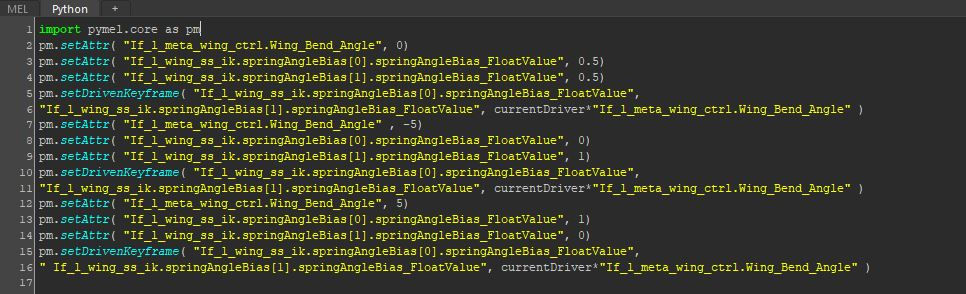
Despite not being able to get the Spring Angle Bias as a keyable attribute, I decided to chose the Spring Solver as it's ability to articulate the four major wing joints worked to a higher degree than the RP-Solver. The image below demonstrates the success of the Spring-Solver paired with the use of Set Driven Keys to achieve the wing fold.

SCALING RIG

To scale the crane rig, group the root joint of the skeleton to itself and name the new group 'Skele_grp'. Select the new Skele_grp and mesh and constrain -> Scale.
,
Throughout this project I have been attentive to my outliner, removing unnecessary items and keeping up to date with naming conventions in order to keep the navigation and readability clear.
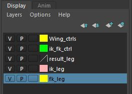
Through testing various techniques and methods in this project, I have found it helpful to make use of the layers window for certain joints and controllers. Here there is layers for FK IK right leg and Wing controls. This tool has enabled me to work with a cleaner workflow.
Outcome

Finishing this project has proved to me that the art of rigging has many methods which can be used to resolve a hurdle in the workflow. From initial joint placement to weight painting, there has been much trial and error yet so much practice and expanse of knowledge about Maya's tools and utilities to get the job done.
SHOWREEL
Comments