'Ascent' Wendigo (GAM220)
- mc217227
- Dec 10, 2020
- 10 min read
Updated: May 20, 2021

During the animation pipeline, there has been a temporary model handed to me that is scaled exactly the same as the final wendigo model. This temporary model has been used to for the final Wendigo character rig.
From assessing the wendigo's temp model, it was decided that a biped style rig could be implemented. The only differences are that the 'ankles' are much higher up and the distance between the heel pivot point and the end tow joint is much closer than a human bipeds.
Joint Placement
Beginning with the arms, select front view in the orthographic options and start placing the joints from the clavicle all the way to the wrist joint. For placing finger joints, enter various orthographic viewports to see which one gives you the best opportunity for rough joint placement. For the wendigo, the top view was the best choice to start adding finger joints.
Switching the a side or front view will help you move the joints along the X,Y or Z axis before going into perspective mode the adjust the joints for final placement decisions. Once all of the fingers have been placed correctly the next step is to connect the five finger joints to the wrist joint. Shift select the finger joint and the wrist, click Skeleton -> Connect Joint -> Parent Joint. As the modelled fingers are slender, adjusting the radius of the finger joints is good practice. You can shift select the joints you wish to change size then enter a figure into the Radius box in the Channel Box Editor.

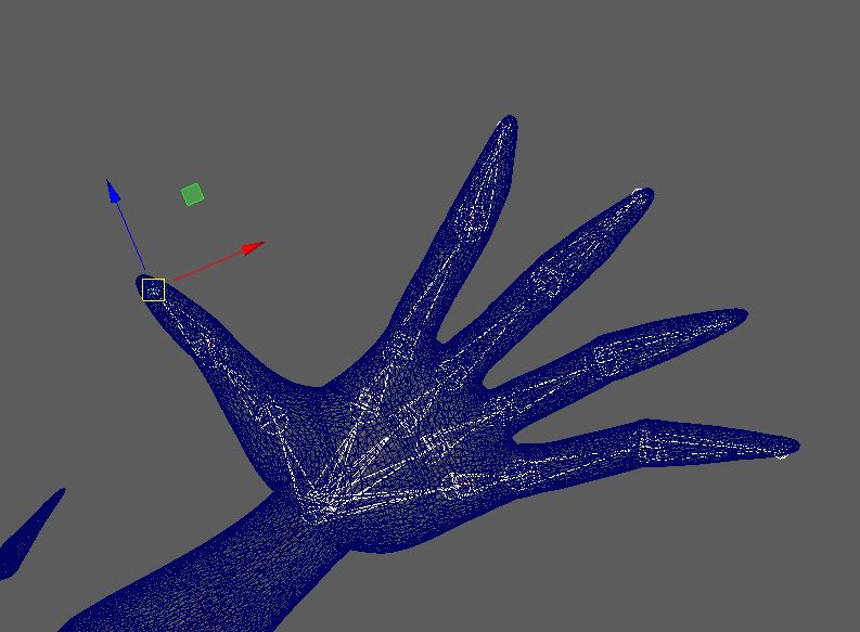
Pictured left are the left hand joints after being placed only using the top view. The joint radius has not been adjusted yet.
The finger joints were set to a radius of 5 and the end joint to a radius of 2 as the fingers taper at the ends. An additional set of joint where placed in the palm to act as the Carpus joints. These joints are here for enhanced grip and metacarpal joint manipulation when it comes to add IK's to them.
Before continuing, the finger and hand joints must have clean channel boxes. Shift select the finger joints and hand joints individually and Modify -> Freeze Transforms. The only boxes that should have figures in are 'Translate'.
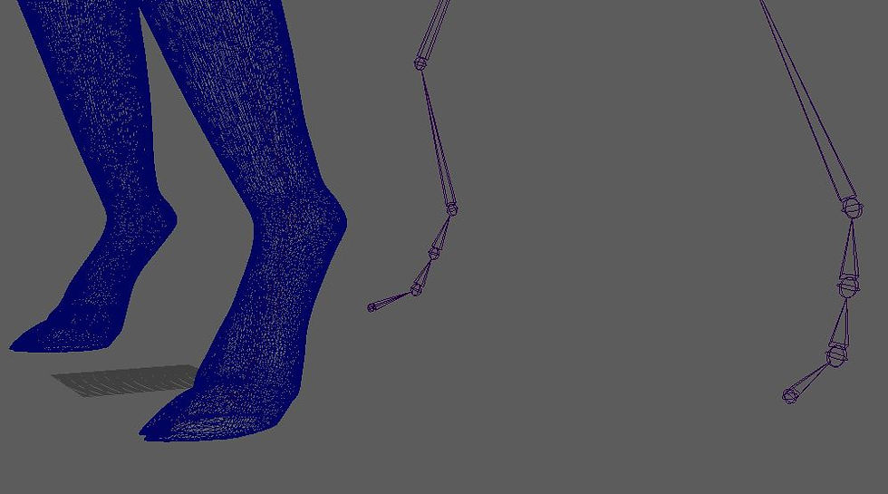
ISSUE: when creating legs joints, the joint chain was started at the end of the toes instead of the hips. This placement would have meant that the Rotate-plane solver IK would have effectively worked upside down. The only was to rectify the issue was to start again with the joint placement; this time starting from the hip and working down to the toes.
(Image below of the incorrect leg joint placements)

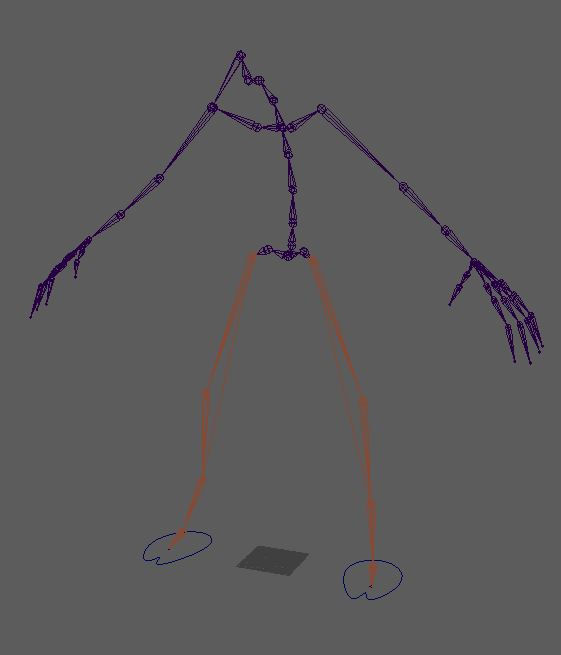
After creating joint placements for the arms, hands and legs, the spine and head joints were placed in while viewing from the orthographic side panel. Viewing from the side panel guides your spine joint placement most effectively as you can easily follow within the meshes back curvature. In the joint skeleton image (shown right), you can see that the legs and arms are yet to be parented to the spine and root of the skeleton. To parent the legs and arms, select both joints you wish to connect and click Skeleton -> Connect Joint -> Parent Joint -> Apply.

Once the the entire skeleton is connected, it is vital that the joint orientation is check before proceeding further with the rig. To assess which direction your joints are pointing, right click the root joint, select hierarchy -> Display -> Transform Display -> Local rotation Axes. Now it is clearly shown where the axes for each skeleton joint are facing. For this Wendigo rig the Y axes were being directed through the orient of the whole body; with exceptions to the toe end, root joint and finger end joints which were using the World Orient.
Adding IK (Legs)
A rotate-plane solver is placed at the hip joint to the ankle. Two single-chain solvers are placed between the ankle and the end toe joint, these two solvers will aid the foot rig performing natural biped foot movements. The first single-chain is placed from the ankle to the ball joint and the next is places from the ball joint to the end toe joint. Now create a foot control, go to Create -> NURBS Curves -> Circle (Ensure 'Interact Creation' is off). Scale and adjust the vertex points as necessary then Edit -> Delete By Type -> History and 'Freeze Transformations'. In order for the three IK handles to be influenced by the foot control, Middle Mouse click the IK handles in the outliner and drag the them over the top of the Foot control and release. This will parent the IK controls to the foot controller. Create a group (ctrl + 'G') for the ball IK and the toe IK. This group will help with pivot placement in the next section.

Controlling Pivot points from the three IK handles will enable the Wendigo's weight to be shifted in the correct locations. These pivots will be able to give the animator additional foot controls in the Channel Box Editor.
Firstly, select the ball and toe group and hit Insert then hold down 'V' to snap this pivot point to the ball joint of the foot. Name this pivot 'Toe Tap', this pivot will be responsible for lifting the toe (Hoof) off from the floor while the heel joint remains planted. Select the Ankle IK and create its own group. Move this ankle pivot the the exact location of the ball joint using the 'v' key to snap it into place. This ankle pivot has the ability to move the heel off of the ground while keeping the toe planted. Having a verb within the Group naming convention help riggers and animators understand what exactly the group has been made for and what action it will carry out when altered through the channel box. This ankle pivot could be named 'Heel_Peel' or 'foot_peel'.
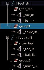
Image left shown how the IK's are grouped and displayed in the outliner for both of the Wendigo's hooves.
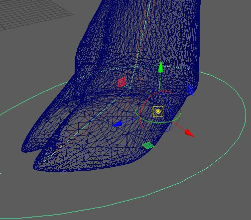
The foot control's pivot should be snapped to the heel's contact point. in this instance the contact point to very close to the ball joint
since the hooves are a different shape to a human foot.
The image below shows the whereabouts of the foot control pivot after being snapped to the contact point.( There are no joints for it to be snapped to so the mesh at the heel is the appropriate location).

Grouping (Foot)
Shift select the 'Toe Tap' and 'Heel Peel' group and hit ctrl + 'G' to make a new group. Move the pivot point of this new group to the ball joint. This will be the group to swivel the ball of the foot.
Now create another group when selecting only the 'Swivel Pivot'. This next group's pivot will be snapped to the toe tip joint. What this will do s allow the entire hoof to life off from the ground. This group was labelled 'Toe Tip Pivot'.
Finally one more pivot group will be created only with the 'Toe Tip Pivot' selected. Snap this pivot point to the ankle joint.
Image left shows 4/5 of the groups in each foot control in the outliner and how they should be parented to one another.
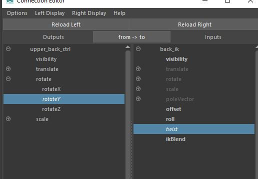
Connecting Pivot Groups to Joint Rotations Using Connection Editor
For animation purposes, having multiple controllable attributes in the channel box and make animating quicker and easier. For this stage there will be five attributes added to the foot control that we can use to control various parts of the hoof. Select the foot control and click Edit -> Add Attributes then begin coping over the group names or their verbs into the 'Long Name' section in the 'Add Attribute' options. Hit 'Add' every time you wish to add a new group name to the 'Long Name' box. As you add all of the five groups you will be able to see what you have typed appear in the channel box editor of the food control with 0 values. Connect the attributes to the rotation values of the five pivot groups can be done with the use of the 'Connection Editor'. While selecting the foot control, click Window -> General Editors -> Connection Editor. Go to 'Left display' and Untick 'non keyable attributes' , this will filter out non keyable attributes and leave you with the appropriate attributes that can be keyed.
On the 'Reload Right' of the connection editor will be where we load up all of the pivot groups. The image below shows the ankle from the foot control selected in the 'Reload Left' and in the 'Reload Right' we can see that the ankle pivot group is loaded and its Rotate X is selected. The channel box will indicate that a connection has been made my highlighting the chosen attribute in yellow (in this instance the Rotate X attribute was highlighted) and italicise both the selected Output and Input. The yellow channel now means that it can drive the rotation value of the chosen pivot group.
Continue clicking 'Reload Right' with the 3 of the pivot groups and select the Rotate X input. For the Swivel group instead of Rotate X choose Rotate Y and hit apply.


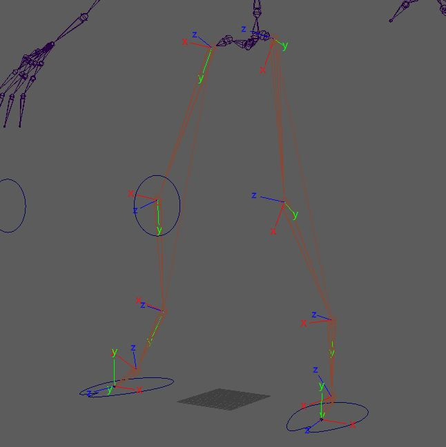
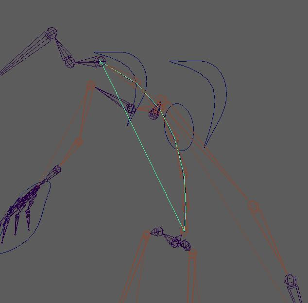
ISSUE: After connecting attributes in the connection editor, my attention was brought to the left knee's joint placement. The knee joint was sticking out of the mesh (this may have gone unnoticed for some time as I had only recently turned the Polygons on. Looking back at the Axes display it became apparent that the left knee's joint axis had been changed.
The Y axis was no longer pointing towards the next joint in the leg chain( As shown by image below). This was fixed in Skeleton -> Orient Joint, then setting Y, Z, Z for the joint orient settings.
Shoulder and Knee Controls
For the knee control create NURBS Circle and scale to appropriate size and rotate to 90 degrees and hit ctrl + 'D' to duplicate for the other knee. Delete by type history and freeze the knee control transforms. Select one control and its accompanying ankle IK handle and go to Constrain -> Poll Vector. Now parent the knee control to the foot control by shift selecting the knee control and the foot control and pressing 'P'. Repeat these steps for the other leg.

For the shoulder controls start by creating a NURBS circle, this will be one of the shoulder controls which will have the power to manipulate the clavicle and shoulder joint. After right clicking -> Control Vertex, the pivot point will need to be vertex snapped to the shoulder joint by pressing Insert then snapping the pivot with the V key. Select shoulder control -> shift select clavicle joint -> constrain -> aim (Options) ensure maintain offset is ticked and World Up Type is 'None'.

For the arms, an additional joint is inserted into the forearms and labelled as a forearm joint. The purpose of this new joint it to aid with the arm twist action. A rotate-plain solver is connected to the shoulder joint and the new forearm joint.
The arm IK handle will create and 'effector' (which can been seen in the image left within the arm hierarchy of the outliner). Select the effector and hit 'insert' key and 'v' snap it to the wrist joint.
Making Hand Controls
Next create a control using a NURBS Circle and group it to itself, this will be classed as an offset group for the hand.
This new group will be temporarily parented to the wrist joint by shift selecting the Hand Offset group and the wrist joint and hitting the 'P' key. Now is the time to change the shape and scale of the controls if you wish, remember to delete the history and freeze their transforms
. Now in the channel box, shift select the attributes and 0 out their values. What this will do is move the Hand Offset to the wrist joint exactly. Hit Shift -> 'P' to unparent the Hand Offset, this will move the offset group and the control back out of the arm hierarchy.
The two images of the channel box editors below show that after temporarily parenting the Hand d Offset group to the wrist and zeroing out the values means that the control has a clean channel editor for the animators to work with while the Hand Offset keeps the values necessary.


Here is what the Wendigo rig looks like now there are IK arms, feet and legs. The next stage is the create and IK spine.

Creating an IK Spine
For the IK spine, switch to the orthographic viewport and click Skeleton -> Create IK Spline Handle (ensure that Auto Parent Curve is turned off). Now its time to place the IK Spline into out joint chain. Select the first back joint nearest to the root joint and also the end of the spine were the neck starts.
It is important for this next step that visibility of the curve that have now been created from the addition of the IK Spline is visible and easy to select.
Go to Show and untick Polygons and Skeleton, this will allow us to see the spine Curve. Right Click the curve and click Control Vertex, you will be able to see small pink dot along the curve, these are the vertex points. Select the top two vertex points and click Deform -> Cluster. The letter 'C' will appear and will have replaced the two pink vertices.
Right click the curve again and choose Control Vertex and select the bottom two vertices and make another cluster.
ISSUE: Pivot point not in usual place - In order to rectify this, hide everything in the 'Show' options then only unhide the NURBS Curves.

After only having the NURBS Curves on show I repeated making th
Image left shows the Cluster not in the correct place.
Image directly below had the Cluster in the correct location.

Adding Spinal Controls
Four spinal controls will be created for the Wendigo, a body ,lower back, back bend and upper back control will be added.
Start by adding a NURBS Circle and snapping it to the root joint. And create another NURBS Circle and snap it to the to joint of the back. Freeze the transforms and delete history for both once adjusting to fit around the model how you desire. Name them appropriately like upper and lower back ctrl.
Image below shows the upper back ctrl being manipulated using Control Vertex to fir the control around the geometry.
Middle mouse click and drag the upper back cluster over the top of the 'upper Back ctrl' and middle mouse click and drag the lower back cluster over the top of the 'lower back ctrl' in the outliner. This will parent them to the control curves and drive the clusters.
Create another NURBS Circle and snap it to the root joint, this will act as the 'Body Ctrl'. Parent the upper and lower back controls to the 'Body ctrl' by shift selecting and hitting 'P'. This body control will now have the capability of moving all of the spine controls.
Next we are going to connect the root joint to the Lower Back Ctrl. Shift select the lower back ctrl and the root joint, go to Constrain -> Parent and make sure 'Maintain Offset' is on.
This action allows for the entire body including the legs to be moved along with the lower back control.
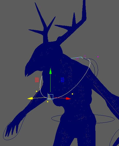
Image below shows the upper and lower back controls in place and parented and constrained accordingly.

Making a Master Control
A master control will be responsibly for controlling there whole body and scale. To make this control, create a NURBS Circle and place it at the base of the rig and scale it up.(Remember to Modify -> Freeze Transformations and delete history)
Middle mouse click and drag the body ctrl to be in the master control hierarchy (As show bottom left image).


Add the rest of the arm and leg controls can be added to the Master Control
Group the back curve and back IK together as create a group in the outliner as these will not be need for animation.
Scaling the Rig
Select the root joint and group it to itself using ctrl -> 'G'. Shift select the new root group and master control and click Constrain -> Scale. This will not let your entire rig to be scaled through the mater control.

Above is a turntable of the rig without rigged hands (for now)
This video demonstrates how the rig moves after implementing the IK handles , constraints and parenting.

Here is the wendigo geometry with the rig visible.


Comments